
 English
 русский
 Español
 عربى
عربى
Content
- 1 A Composite Aluminum Panel Is a Laminated Sandwich Structure, Not a Single Aluminum Sheet
- 2 Core Material and the Fundamental Divide Between PE and FR Panels
- 3 Coating Systems and the PVDF vs. Polyester Durability Spectrum
- 4 Fabrication Methods and the Groove-and-Fold Technique
- 5 Thermal Expansion and the Panel Movement That Must Be Accommodated
- 6 Wind Load Design and the Span Tables That Govern Attachment Spacing
- 7 Joining Methods and the Adhesive Bonding Alternative
- 8 Flatness Standards and the Visual Acceptance Criteria
- 9 Service Life and the Coating Warranty as a Performance Indicator
A Composite Aluminum Panel Is a Laminated Sandwich Structure, Not a Single Aluminum Sheet
Composite aluminum panels are engineered building materials consisting of two thin aluminum sheets—typically 0.3 to 0.5 millimeters thick each—thermally bonded under continuous heat and pressure to a non-aluminum core material that ranges from 2 to 5 millimeters in thickness. The resulting sandwich panel, typically 3 to 6 millimeters in total thickness, exhibits a flexural rigidity far greater than a solid aluminum sheet of equivalent weight. The aluminum skins provide tensile strength, weather resistance, and a surface suitable for architectural coating systems, while the core transfers shear stress between the skins and provides the panel's flatness and impact resistance. This laminated construction is what makes a 4-millimeter composite panel remain dead-flat across a 1.2-meter span, whereas a solid aluminum sheet of the same weight would exhibit visible waviness and oil-canning when subjected to temperature changes. The bond between the aluminum skin and the core is achieved through a continuous thermoplastic adhesive film—typically a modified polyethylene copolymer—that is heat-activated during the panel lamination process and achieves peel strengths exceeding 15 N/25mm when tested in accordance with ASTM D1781.

Core Material and the Fundamental Divide Between PE and FR Panels
The core material is the defining component of a composite aluminum panel, and the choice between core types determines the panel's fire performance classification, cost, weight, and suitability for specific building applications. The standard core for non-fire-rated applications is low-density polyethylene, which has a density of approximately 0.92 to 0.95 g/cm³ and a limiting oxygen index of approximately 17%, meaning it will burn readily in normal atmospheric conditions. PE-core panels account for the majority of composite aluminum panels used globally in signage, interior decoration, and non-regulated exterior applications. The alternative core technology for fire-rated applications is a mineral-filled core, where the polyethylene matrix is loaded with 30% to 70% by weight of fire-retardant mineral fillers—typically aluminum trihydroxide or magnesium dihydroxide—that absorb heat through endothermic decomposition, release water vapor that dilutes combustion gases, and leave a ceramic char layer that insulates the unburned core. These mineral-filled FR core panels achieve a limiting oxygen index above 30%, which classifies the material as self-extinguishing, and they can meet the requirements of ASTM E84 Class A, EN 13501-1 Class B-s1-d0, or equivalent national fire standards. A third, less common core type is a corrugated or honeycomb aluminum core that is used for high-stiffness, all-metal applications where thermal expansion compatibility between skin and core is required.
The Fire History and the Regulatory Response
The global regulatory environment for composite aluminum panels changed fundamentally after several high-rise building fires in which PE-core panels on exterior cladding contributed to rapid vertical flame spread. These incidents led to widespread code revisions that now prohibit the use of PE-core composite panels on exterior cladding for buildings above a certain height threshold—typically 18 meters or four stories, depending on the jurisdiction. The replacement requirement is that exterior cladding panels must have a mineral-filled FR core or must be of an alternative construction, such as solid aluminum sheet or a different non-combustible cladding material. The specific testing requirement varies by country: in the United States, the relevant standard is NFPA 285 for the full-scale multi-story wall assembly test; in the United Kingdom and many Commonwealth countries, it is BS 8414; in the European Union, EN 13501-1 classification is referenced in national building codes. The practical consequence for specifiers is that the core material must be verified through third-party test reports specific to the panel brand and model being specified, not assumed from generic product literature.
Coating Systems and the PVDF vs. Polyester Durability Spectrum
The aluminum skins on a composite aluminum panel are coated with an architectural finish that determines the panel's color retention, gloss retention, chalk resistance, and corrosion protection over decades of exterior exposure. The coating system is applied to the aluminum coil before it is laminated into a composite panel, using a continuous coil-coating process that applies a chromate conversion coating pretreatment followed by a primer layer and a topcoat, each cured at a peak metal temperature of 230 to 250 degrees Celsius. The topcoat chemistry divides into two primary families. Polyvinylidene fluoride coatings, typically formulated as a 70% PVDF / 30% acrylic resin blend, are the standard for exterior architectural applications and carry a performance warranty of 15 to 30 years against color fade and chalk. The carbon-fluorine bond in PVDF is one of the strongest chemical bonds in organic chemistry, and it resists degradation from UV radiation, acid rain, and salt spray. Polyester coatings, either standard polyester or silicone-modified polyester, are less expensive and are used for interior applications or for exterior signage with a shorter service-life expectation of 5 to 10 years. The color range available in PVDF is narrower than in polyester because the high-temperature curing requirements of PVDF limit the pigment chemistries that are thermally stable, which is why certain bright reds, oranges, and yellows are only available in polyester formulations.
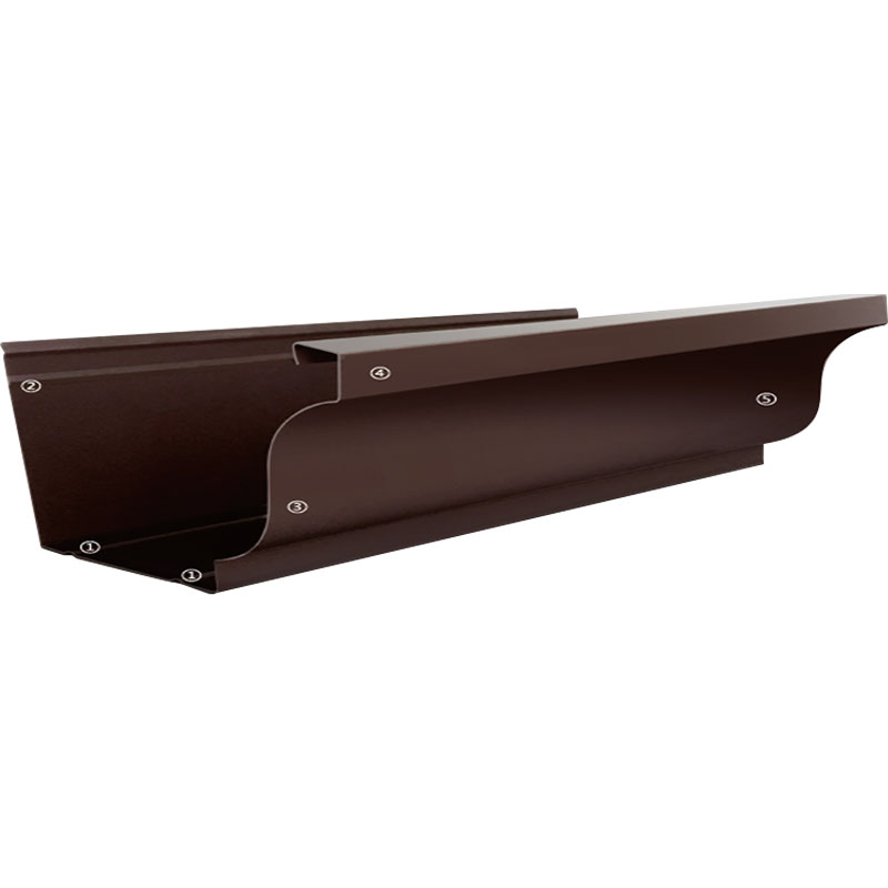
Fabrication Methods and the Groove-and-Fold Technique
Composite aluminum panels are shaped into architectural elements primarily through the groove-and-fold technique, in which a V-shaped groove is routed into the back face of the panel through the aluminum skin and most of the core, leaving the front aluminum skin and a thin layer of core material intact to act as a hinge. The panel is then bent along this groove line to form a crisp, straight corner with a bend radius determined by the remaining material thickness. The routing depth is critical: too shallow and the fold will spring back or crack the front skin; too deep and the router bit will score or penetrate the front aluminum surface, creating a visible line on the finished face. The correct routing depth leaves 0.3 to 0.4 millimeters of material—essentially the front aluminum skin plus approximately 0.1 millimeters of core—intact below the groove. The angle of the V-groove determines the finished corner angle: a 90-degree groove produces a 90-degree corner, a 135-degree groove produces a 45-degree return. The groove width, tool selection, and feed rate must be matched to the panel thickness and core type; PE cores route cleanly at higher feed rates than mineral-filled FR cores, which are more abrasive and require carbide or diamond-tipped routing tools to maintain edge quality over production runs. After folding, the corner can be reinforced with aluminum angle brackets bonded into the interior corner with structural adhesive to provide additional stiffness and to prevent the corner from opening under wind load cycling.
CNC Routing and the Dust Extraction Requirement
The V-grooving process generates a substantial volume of core material dust that is both a nuisance and a potential fire hazard. PE core dust is combustible and, when suspended in air at the right concentration, can form an explosive dust cloud. FR mineral-filled core dust is heavier and less combustible but is abrasive to machine tool ways and bearings. The routing station must be equipped with a high-efficiency dust extraction system that captures swarf at the tool point before it becomes airborne, and the collected dust must be disposed of in accordance with local regulations for combustible or mineral waste as appropriate. The dust extraction ductwork for PE core routing should be grounded and bonded to dissipate static electricity, and the dust collection bin should be emptied and the filter elements cleaned on a schedule that prevents the accumulation of combustible material inside the dust collection system.
Thermal Expansion and the Panel Movement That Must Be Accommodated
Composite aluminum panels expand and contract with temperature changes, and the amount of movement is primarily determined by the aluminum skins. The coefficient of thermal expansion for aluminum is approximately 2.4 × 10⁻⁵ per degree Celsius, meaning a 3-meter-long panel subjected to a 60-degree Celsius temperature swing between winter night and summer sun will change in length by approximately 4.3 millimeters. This movement must be accommodated in the panel joint design and in the attachment system. Panels that are rigidly fixed at multiple points without allowance for expansion will buckle outward between the fixed points when heated—a failure mode known as oil-canning that is permanent once it occurs because the aluminum skins yield in compression and do not return to flat when cooled. The standard joint width for composite panel systems ranges from 10 to 20 millimeters, with the wider joint specified for darker colors that absorb more solar energy and reach higher peak temperatures. The attachment system typically uses a combination of fixed-point anchors that resist wind load and sliding-point anchors that allow thermal movement, with the fixed points positioned at the panel centerline so that expansion occurs symmetrically toward both edges. The routing and folding of the panel edges into cassettes or trays changes the thermal expansion behavior: a fully folded tray with returns on all four edges is stiffer than a flat panel and may require different joint widths and attachment spacing than the flat panel from which it was fabricated.
Wind Load Design and the Span Tables That Govern Attachment Spacing
The structural design of a composite aluminum panel cladding system is governed by span tables that specify the maximum allowable spacing between attachment points for a given panel thickness, core type, and design wind pressure. A 4-millimeter PE-core panel with a 0.5-millimeter aluminum skin, supported on four edges with perimeter framing at 600-millimeter centers, can typically resist a design wind pressure of 1.5 to 2.0 kPa with a deflection limit of L/60. Increasing the panel thickness to 6 millimeters or reducing the framing centers to 400 millimeters increases the wind load capacity proportionally. The deflection limit is set not by structural failure—composite panels are highly ductile and will not fracture under wind load—but by serviceability: excessive deflection causes visible waviness in reflected light and can open the panel joints beyond the engagement range of the weather seals. The span tables are published by panel manufacturers and are specific to each panel construction; a span table for a PE-core panel cannot be applied to an FR-core panel, because the mineral-filled core has a different shear modulus that affects the panel's flexural behavior. The attachment system itself—typically aluminum extrusions with a rivet, screw, or adhesive fixing to the panel—must also be designed for the wind load, and the fasteners must have sufficient edge distance in the aluminum skin to prevent tear-out under negative wind pressure that pulls the panel outward from the building.
| Core Type | Composition | Fire Performance | Typical Application | Density (g/cm³) |
|---|---|---|---|---|
| PE (Polyethylene) | Unfilled LDPE | Combustible, LOI ~17% | Signage, interior, low-rise exterior | 0.92–0.95 |
| FR Mineral-Filled | PE + ATH/MDH (30–70%) | Self-extinguishing, LOI >30% | High-rise exterior, regulated cladding | 1.30–1.60 |
| Aluminum Honeycomb | Aluminum foil honeycomb | Non-combustible | High-stiffness, aviation, marine | Varies, lightweight |
Joining Methods and the Adhesive Bonding Alternative
The traditional method for assembling fabricated composite panel elements—such as cassette returns, stiffener channels, and cleats—is mechanical fastening with aluminum blind rivets or stainless steel screws. Mechanical fastening is reliable and inspectable, but it creates point loads at each fastener, leaves fastener heads visible on the panel face or rear, and can be incompatible with the aesthetic requirements of high-end architectural work. An alternative method that has gained acceptance for premium applications is structural adhesive bonding using two-part epoxy or acrylic adhesives specifically formulated for bonding aluminum. The adhesive is applied in a continuous bead along the joint between the panel and the attachment profile, and the assembly is fixtured until the adhesive reaches handling strength. A properly designed adhesive joint distributes the load continuously along the bond line rather than concentrating it at discrete fastener points, which allows the use of thinner aluminum skins without fastener dimpling and eliminates the thermal bridging that metal fasteners create. The adhesive system must be validated for the specific panel coating because the bond is made to the coating surface, not to bare aluminum, and the coating's surface energy and adhesion to the aluminum substrate determine the ultimate bond strength. A minimum lap shear strength of 5 MPa on the actual coated panel surface is a typical acceptance criterion for structural adhesive bonding of composite panel attachments.
Flatness Standards and the Visual Acceptance Criteria
The flatness of installed composite aluminum panels is evaluated by visual observation under specific lighting conditions, and the acceptance criteria are defined in industry standards such as AAMA 508 and EN 438-6. The panel surface, when viewed at an oblique angle under diffuse natural lighting or equivalent artificial lighting, should not exhibit oil-canning, defined as visible waviness or ripples that distort reflected images, greater than 2 millimeters in amplitude per 300 millimeters of panel length. Localized defects such as dents, creases, or fastener dimpling that are visible from a distance of 3 meters under normal viewing conditions are not acceptable. The flatness of a composite panel is determined by the quality of the aluminum skins, the uniformity of the core, the lamination process parameters, and the handling and installation procedures. A panel that has been dropped on a corner during handling, or a panel that has been installed with its attachment points out of plane, will show flatness defects that are installation-related rather than manufacturing-related. The distinction matters because the responsibility for remediation lies with different parties, and the flatness inspection should be performed after the panel installation is complete and the panels are subject to their design wind and temperature conditions, not during installation when the panels may be temporarily stressed by handling and alignment forces.
Service Life and the Coating Warranty as a Performance Indicator
The service life of a composite aluminum panel system is driven primarily by the durability of the coating on the exterior aluminum skin, because the aluminum itself and the core material are inherently resistant to environmental degradation. A PVDF-coated panel installed in a non-marine, non-industrial environment can be expected to maintain its color and gloss within the warranty specifications for 20 to 30 years, after which gradual chalking and color fade become measurable but not necessarily aesthetically objectionable. The coating warranty is therefore a meaningful performance indicator: a manufacturer that offers a 20-year film integrity, color, and gloss warranty on a PVDF finish has validated that finish through extensive accelerated weathering to the equivalent of that service period. The warranty is also an indicator of the coating's chalk resistance: chalking is the degradation of the resin at the coating surface, which releases pigment particles that can be wiped off as a colored powder, and it represents the beginning of the coating's end-of-life phase. A panel that has begun to chalk significantly is still structurally intact, but its appearance will continue to degrade, and recoating a composite panel is generally not economically viable compared to replacement. The structural life of the panel—the integrity of the bond between the aluminum skins and the core—typically exceeds the coating life, and a 30-year-old panel with a chalked coating may still be structurally serviceable, although removal and replacement would be triggered by aesthetic rather than safety considerations.


